

Typical application showing tool testing pin contacts.
The quality assurance test most often overlooked is contact retention (proper seating of power contacts). This important test can now be performed simply and in a matter of seconds with the JRready retention testing tools for power conatcts.

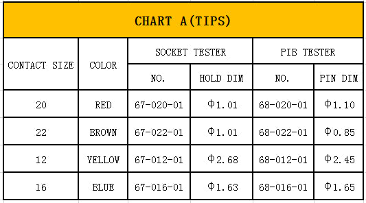
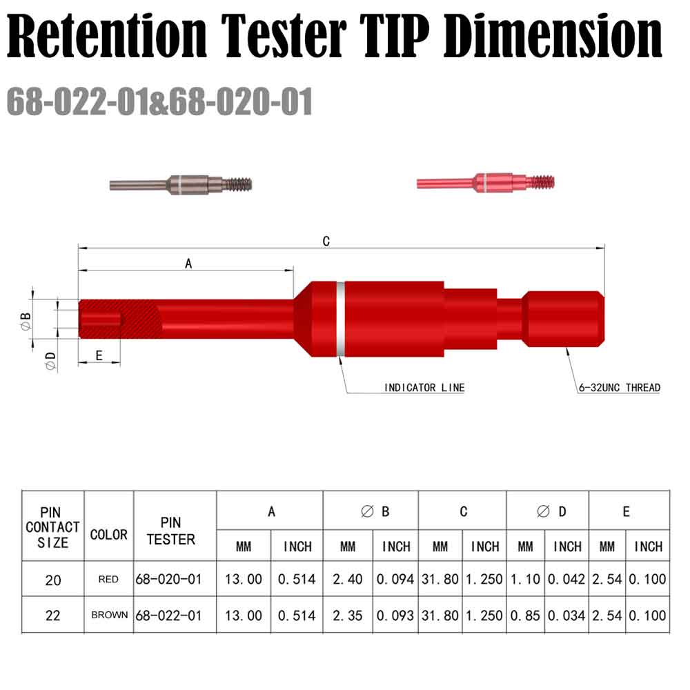
These tools check the retention of pins and sockets in electrical connectors by indicating when propper pressure has been applied. Each tool body is set for a different poundage range (see chart A on back of this page). The tester tips are color coded for specific sizes and designated for pins or sockets. Use pin end tipes to test sockets and socket end tips to test pins. All tips are replaceable.
The tools can be preset at the factory to your request.Insert tester into a contact so that the tester and contact are in a straight line. Hold in this position throughout the testing procedure. Apply pressure to tester until the indicator band is in-line with the body. If contact is still fimly retained, the retention is satisfactory.
USE OF TOOL
- use pin tester tip to test pin contact's retention, and use socket tester tip to test socket contact' 's retention.
- pre-set tool at a specific force according to standards
- choose a tip refer to contact size in chart A, remove head lock screw(use wrench 5/64), and fit tip into this thread hole.
- insert tester into contact's head. Tool must be in a straight line with contact.
- wear safety glasses W hen use
- Apply pressure toward contact until slide aligns with indicator line, and keep tester in position at least 2 seconds, contact should remain in place if retention force is up to standard.
- tool should be checked in every 2000 times to verify the indicator line force, and should be put back in tool box with a dry and clean place if used up.
- tips fit standard M39029.
TOOL ADJUSTMENT
- Each tool was adjusted at a specific force in factory and could be re-adjusted by customer if necessary。
- Remove hand protector, loose lock nut(open-ended spanner 5/16) to allow free movement of adjustment screw.
- Put tool in tensile equipment for precise calibration. If precise calibration isn't required or can't find proper a tensile equipment, you can set the tool by hand.
- Holding the tool firmly by hand on a weight indicating device, and apply axial force with a specific weight. Tool must be in a axial line with weight indicating device, and slide should pass over the indicator line.
- Adjust tool to required force by turning adjustment screw with a screwdriver. Clockwise to increase and counter-clock wise to decrease, and slide should be pull back. When required value is achieved, slide should be aligns with indicator line. Hold tool in position and tighten lock nut firmly. Tool is now set.
- Inspection stickers should be used to seal hand protector onto tool body, in order to avoid any unintentional touch with the adjustment screw.